Silicon steel sheets, also known as silicon steel plates, are an indispensable magnetic material in the electrical engineering field. They are refined from electrical silicon steel with a silicon content of 0.8%-4.8% through hot and cold rolling processes, and are typically no more than 1 mm thick, hence the name “thin sheet.” Broadly speaking, silicon steel sheets belong to the category of sheet metal, but they are classified as a separate category due to their unique electrical properties and wide range of applications. Whether in the power, telecommunications, or instrumentation industries, silicon steel sheets play a crucial role, serving as a key material for ensuring the efficient and stable operation of equipment.
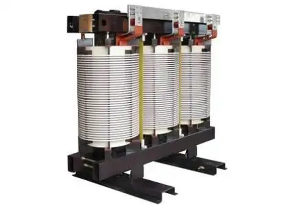
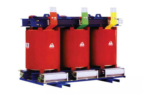
Most commonly used transformer cores are made of silicon steel sheets. Silicon steel is a type of steel containing silicon, with its silicon content controlled within the range of 0.8% to 4.8%. The primary reason for choosing silicon steel as the transformer core material is its excellent magnetic permeability. In a energized coil, silicon steel can generate a strong magnetic induction intensity, thereby enabling a reduction in transformer size. In practical applications, transformers always operate under alternating current. Besides power losses caused by coil resistance, the core also experiences power losses under the magnetization effect of alternating current, commonly referred to as “iron losses.” These iron losses mainly originate from two factors: “hysteresis losses” and “eddy current losses.”
Hysteresis losses are losses generated during the magnetization process of the core due to hysteresis. Their magnitude is closely related to the area enclosed by the hysteresis loop of the material. Fortunately, the hysteresis loop of silicon steel is relatively narrow, so using silicon steel as the transformer core can significantly reduce hysteresis losses, thereby greatly reducing the heat generated by the core.
However, the aforementioned advantages of silicon steel do not mean that we can directly use a single piece of silicon steel to make the core. To further reduce another type of iron loss—eddy current loss—the iron core is machined into a sheet shape. This sheet structure can effectively reduce eddy current loss and further improve the efficiency of the transformer.
During transformer operation, the alternating current in its coils generates alternating magnetic flux. This changing magnetic flux induces current in the iron core, which circulates in a plane perpendicular to the direction of the magnetic flux, known as eddy currents. Eddy current losses also cause the iron core to heat up. To reduce these losses, the transformer core is typically made of stacked silicon steel sheets that are insulated from each other. This allows eddy currents to pass through a smaller cross-section in a narrow loop, thus increasing the resistance in the eddy current path. Simultaneously, the silicon element in the silicon steel increases the material’s resistivity, further contributing to reducing the effects of eddy currents.
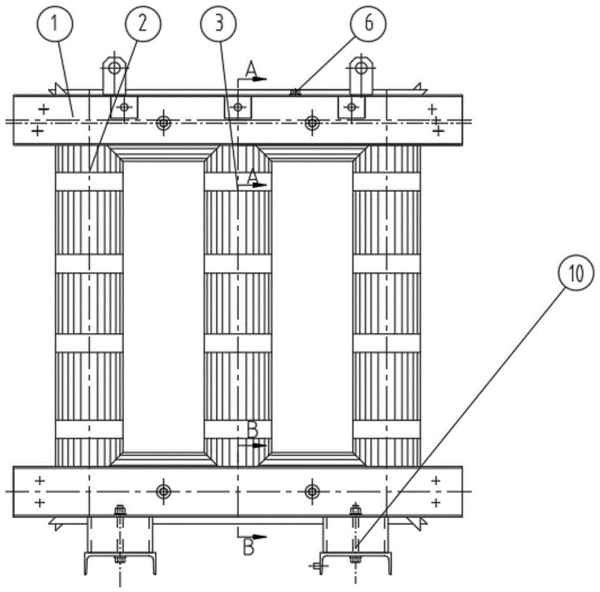
Transformer cores are typically made of cold-rolled silicon steel sheets with a thickness of 0.35mm or the design requirement. These sheets are cut into long strips according to the required core dimensions and then stacked into a “日” (sun) or “口” (mouth) shape. Theoretically, the thinner the silicon steel sheets and the narrower the spliced strips, the better the effect on reducing eddy currents. This not only reduces eddy current losses and temperature rise but also saves on silicon steel material.
In actual manufacturing, other factors also need to be considered. Simply pursuing the aforementioned effects might increase manufacturing time and reduce the effective cross-section of the core. Therefore, when manufacturing silicon steel sheet cores, we need to comprehensively consider various factors, weigh the pros and cons, and choose the most suitable size.
Transformers operate based on the principle of electromagnetic induction. Two windings are wound on a closed core column: a primary winding and a secondary winding. When an AC power supply voltage is applied to the primary winding, an alternating current is generated, thus establishing a magnetomotive force (MOF). Under the influence of this MOF, an alternating main magnetic flux is generated in the core.
Transformers can perform voltage step-up and step-down functions, which are based on profound physical principles. Lenz’s law reveals the mystery: when the alternating current in the primary winding generates a magnetic flux, it attempts to oppose the change in the original magnetic flux. Specifically, when the original magnetic flux increases, the magnetic flux generated by the induced current will be in the opposite direction to the original magnetic flux. In this way, a low-level alternating voltage is generated in the secondary winding, whose induced magnetic flux cancels out the main magnetic flux of the primary winding. The core, as the magnetic circuit core of the transformer, plays a crucial role.
1. Classification of Silicon Steel Sheets
Silicon steel sheets can be broadly classified into two categories based on their silicon content: low-silicon and high-silicon. Low-silicon steel sheets, with a silicon content below 2.8%, possess a certain mechanical strength and are commonly used in motor manufacturing, hence the industry term “motor silicon steel sheets.” High-silicon steel sheets, with a silicon content between 2.8% and 4.8%, offer excellent magnetic properties but are more brittle, thus primarily used in transformer core manufacturing, and are known as “transformer silicon steel sheets.” It’s worth noting that there isn’t an absolute boundary between these two types of silicon steel sheets in practical applications; high-silicon steel sheets are also frequently used in the manufacture of large motors.
2. Processing Technology of Silicon Steel Sheets
The main processing technologies for silicon steel sheets include hot rolling and cold rolling. Cold rolling is further subdivided into non-oriented and grain-oriented types. Cold-rolled silicon steel sheets are renowned for their uniform thickness, superior surface quality, and high magnetic properties. With the continuous advancement of industrial technology, hot-rolled silicon steel sheets are gradually being replaced by cold-rolled silicon steel sheets. In particular, my country has clearly put forward a policy to stop using hot-rolled silicon steel sheets, namely the so-called “cold-rolled instead of hot-rolled” strategy.
3. Performance Indicators of Silicon Steel Sheets
a. Low Iron Loss: This is a key indicator of silicon steel sheet quality. Globally, countries classify silicon steel sheets based on iron loss values; lower iron loss corresponds to a higher grade and, consequently, superior product quality.
b. High Magnetic Induction Intensity: Under the same magnetic field conditions, silicon steel sheets with high magnetic induction intensity can generate higher magnetic flux density. This allows for a reduction in the size and weight of the manufactured motor or transformer core, thus saving resources such as silicon steel sheets, copper wire, and insulation materials.
c. High Stacking Factor: The smoothness, flatness, and thickness uniformity of the silicon steel sheet surface directly affect the stacking factor of the core. Silicon steel sheets with excellent surface quality naturally have a higher stacking factor.
d. Good Stamping Properties: This is particularly important for manufacturing cores for small and micro motors, as it directly affects the core manufacturing process and yield.
e. Good Adhesion and Weldability of the Surface to the Insulating Film: This is a crucial guarantee for ensuring that the silicon steel sheet maintains good performance during subsequent processing and use. 6. Magnetic aging. This refers to the ability of silicon steel sheets to maintain stable magnetic properties after a period of use, without significant degradation.
f. Annealing and pickling treatment. Silicon steel sheets must undergo annealing and pickling processes before leaving the factory to ensure their performance and quality meet standard requirements.